We completely reworked the grasshopper file from Tuesday so that it’s subdivision isn’t limited to however many columns are called out. The patterns are controlled and expanded now by boolean patterning and the surfacing can be manipulated by the points / surface layout.
We began with this folding motif from the pdf, analyzing the pattern in rhino/illustrator to break it down into modules and proportions. We were drawn to the pattern because of the undulating edge profile, and our early physical test indicated rows could be aligned into a foldable sheet.
GRASSHOPPER side of things
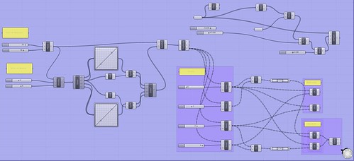
The last week or so has been spent wrapping out heads around grasshopper and the pattern. Our first definitions relied heavily on band-aid techniques such as simple translation, but were eventually re-worked into this definition, which is modifiable in the x and y scale and magnitude.
The definition relies heavily on the mirror command, however, which we feel is not the most efficient way to construct the pattern, especially once we want to introduce more variations. Therefore, the current work has been trying to work with data for longer, before constructing lines of the modules, because it is easier to manipulate and reference data.
PHYSICAL side of things
We mostly worked with printers and physical cuts, in lieu of constructing the grasshopper definition side by side, and limited experience with laser cutting. Folding our pattern yielded interesting results – at first it was quite resistant to folding, but then we realized we were pushing the wrong modules.
The points marked in the image can converge to an almost touching position, which makes the system quite dynamic . There is a bit of bending observed along the ridge folds, which we think we can solve by introducing some connecting ridge fold lines.
CURRENT workings / integration
Laser cutting our grasshopper definition will tell us more than our physical models have been able to reveal, because we are not sure if the bending on the ridge folds is due to overworking the material, or is a problem which can by solved.
The final result seeks to emulate the random character of our initial variations rather than using a normative gradient of variability dependent on surface variation. Every triangle is a unique size and is dependent from a rationalized yet seemingly random base curve division.
After developing the base pattern with Iterations 1 and 2 we wanted explore variation. With the 3rd, 4th and 5th iterations we used the graph mapper tool which proved problematic when it came to folded the paper. With the last iteration we decided to give the pattern a varying offset using an attractor point.
In addition, here is a compilation of the final photos of our final cut/fold. The image in the top-left is (from right to left) a series of process developments where we discovered from our failures what worked and what was simply not happening. http://imageshack.us/photo/my-images/254/tuckerdavidorigamiphoto.jpg/

Here are our screenshots,


The 1st is the grasshopper definition of the 3d form, the 2nd being the resulting lines and form.
//Tuck and Dave
And the Cut-out photo
http://imageshack.us/photo/my-images/84/cutoutphoto.jpg/
Thanks
Images:
Overall – http://i.imgur.com/DIRN9.jpg
Ghopper Input – http://i.imgur.com/CzWWw.jpg
Rhino Output – http://i.imgur.com/ErgCp.jpg
Cut Pattern – http://i.imgur.com/WrkW6.jpg
Stephen, Emily and Nina
team dFabulous
(updates for panelization)
Images of Final Models:
Self-supporting (structural) panel – http://imgur.com/LLxbl
Fastened strip-modules panel – http://imgur.com/fDCC6
Compression (column) panel – http://imgur.com/8o2Qy
Here are the new cut file screenshots…using the same definition as before but coming at if from 2D development of the unfolded sheet.
[URL=http://imageshack.us/photo/my-images/843/cutfilelongmodule.jpg/][IMG]http://img843.imageshack.us/img843/7200/cutfilelongmodule.jpg[/IMG][/URL]
Uploaded with [URL=http://imageshack.us]ImageShack.us[/URL]
[URL=http://imageshack.us/photo/my-images/13/cutfilesquaremodule.jpg/][IMG]http://img13.imageshack.us/img13/2597/cutfilesquaremodule.jpg[/IMG][/URL]
Uploaded with [URL=http://imageshack.us]ImageShack.us[/URL]
Well the embed didnt work so..here are the links.
http://imageshack.us/photo/my-images/13/cutfilesquaremodule.jpg/
http://imageshack.us/photo/my-images/843/cutfilelongmodule.jpg/
We completely reworked the grasshopper file from Tuesday so that it’s subdivision isn’t limited to however many columns are called out. The patterns are controlled and expanded now by boolean patterning and the surfacing can be manipulated by the points / surface layout.
current:
http://imageshack.us/f/9/blog01b.jpg/
before:
http://imageshack.us/f/29/blog03z.jpg/
manipulated form:
http://imageshack.us/f/684/blog02q.jpg/
Folded pattern


Various angle studies:
15 degree angle
45 degree angle
60 degree angle
75 degree angle
folding template for initial studies
opposing angles
extreme overlap
angled pattern
angle variation… unsuccessful
laser cut model with variation
determining structure profile
beginners basics
We began with this folding motif from the pdf, analyzing the pattern in rhino/illustrator to break it down into modules and proportions. We were drawn to the pattern because of the undulating edge profile, and our early physical test indicated rows could be aligned into a foldable sheet.

GRASSHOPPER side of things

The last week or so has been spent wrapping out heads around grasshopper and the pattern. Our first definitions relied heavily on band-aid techniques such as simple translation, but were eventually re-worked into this definition, which is modifiable in the x and y scale and magnitude.
The definition relies heavily on the mirror command, however, which we feel is not the most efficient way to construct the pattern, especially once we want to introduce more variations. Therefore, the current work has been trying to work with data for longer, before constructing lines of the modules, because it is easier to manipulate and reference data.
PHYSICAL side of things
We mostly worked with printers and physical cuts, in lieu of constructing the grasshopper definition side by side, and limited experience with laser cutting. Folding our pattern yielded interesting results – at first it was quite resistant to folding, but then we realized we were pushing the wrong modules.

The points marked in the image can converge to an almost touching position, which makes the system quite dynamic . There is a bit of bending observed along the ridge folds, which we think we can solve by introducing some connecting ridge fold lines.
CURRENT workings / integration
Laser cutting our grasshopper definition will tell us more than our physical models have been able to reveal, because we are not sure if the bending on the ridge folds is due to overworking the material, or is a problem which can by solved.
Mitchell Lorberau / Blair Ekleberry
Initial Grasshopper Definition
Final Grasshopper Definition
Laser Template File (2D)
Final Physical Model 1
Final Physical Model 2
Real Final Physical Model 3
Final Model Photos:
http://imageshack.us/photo/my-images/13/model04t.jpg/
http://imageshack.us/photo/my-images/827/model03k.jpg/
http://imageshack.us/photo/my-images/827/model01i.jpg/
http://imageshack.us/photo/my-images/801/model02.jpg/
Final Definition:
http://imageshack.us/photo/my-images/810/deffinal.jpg/
http://imageshack.us/photo/my-images/403/deffinalscript.jpg/
Definition Sequence:
http://imageshack.us/photo/my-images/853/definitionsequence.jpg/
*from slightly parametric and ordered to surface manipulation to random base curve manipulation through graph slider
The final result seeks to emulate the random character of our initial variations rather than using a normative gradient of variability dependent on surface variation. Every triangle is a unique size and is dependent from a rationalized yet seemingly random base curve division.
After developing the base pattern with Iterations 1 and 2 we wanted explore variation. With the 3rd, 4th and 5th iterations we used the graph mapper tool which proved problematic when it came to folded the paper. With the last iteration we decided to give the pattern a varying offset using an attractor point.
3rd Iteration


4th Iteration


5th Iteration

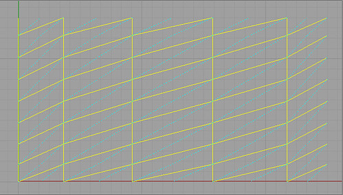
Final Grasshopper Definition and rhino Output

Point attractor for the offset

In addition, here is a compilation of the final photos of our final cut/fold. The image in the top-left is (from right to left) a series of process developments where we discovered from our failures what worked and what was simply not happening.
http://imageshack.us/photo/my-images/254/tuckerdavidorigamiphoto.jpg/
http://flic.kr/s/aHsjwmeW7i
Our process models, initial parametric iterations, and diagram of definition.